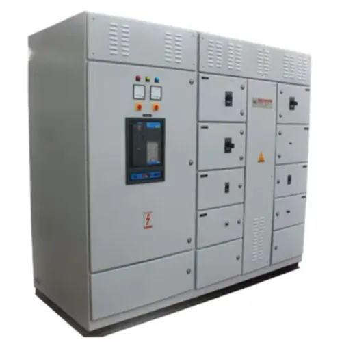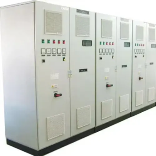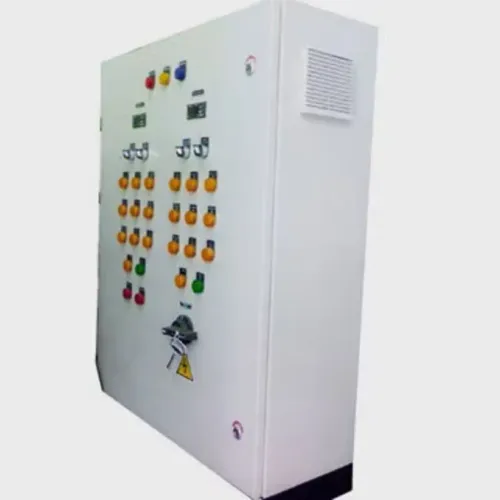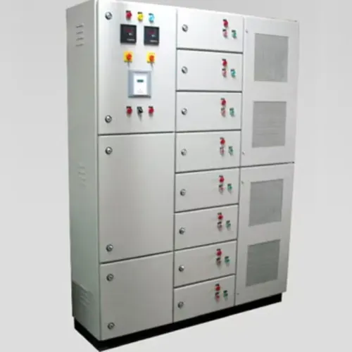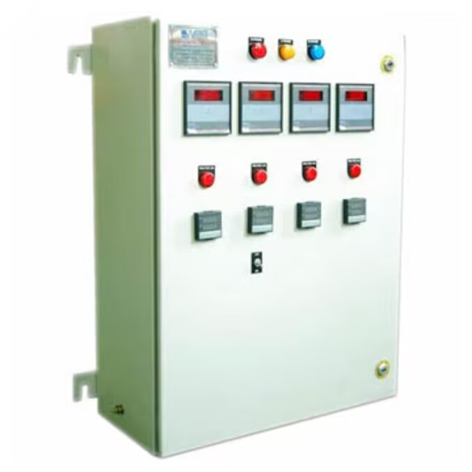
A drive panel specification can fail before fabrication if the supplier lacks motor data, fault-level information, thermal assumptions, cable details, or a defined test plan. By the end, you will have a practical question list for comparing designs, identifying hidden costs, and approving a panel that can be installed, commissioned, maintained, and expanded safely.
Key takeaways
- Provide nameplate data, starting method, load profile, and duty cycle.
- Confirm short-circuit rating, harmonic limits, braking method, and protective devices.
- Require enclosure heat calculations with drive losses, ambient temperature, and ventilation details.
- Define FAT documents, acceptance tests, spare space, and change-approval rules.
Give the Supplier the Complete Motor and Drive Data Set
Before a supplier freezes the panel design, provide a nameplate-level motor record, a real-world load profile, and the intended drive arrangement. Missing data leads to an undersized drive, nuisance trips, or cable damage discovered after wiring is complete.
1. Motor: motor voltage, full-load current, rated power, frequency, pole count or base speed, motor type (induction, synchronous, or servo), insulation capability, starting method, and service factor.
2. Load: driven equipment, torque-speed requirement, minimum and maximum speed, duty cycle, acceleration and deceleration time, starts per hour, inertia, regenerative energy, braking method, and whether the load can coast or must stop quickly.
3. Drive: variable-frequency drive or servo drive, manufacturer and model, input voltage and phase, required output current, overload rating and duration, speed range, switching or carrier frequency, feedback device, and control method such as V/f, sensorless vector, or closed-loop control.
4. Motor circuit: motor-lead length, cable construction, EMC screening, motor grounding arrangement, termination method, insulation rating, and whether the cable shares a tray with power or control wiring. Long cables can require a dV/dt filter, sine-wave filter, shaft-grounding device, or insulated bearing.
5. Supply and options: available input voltage, phase, fault level, earthing system, supply fluctuations, bypass requirement, alternate supply, and the required transfer behavior after a drive fault or control-power loss.
Confirm every assumption in the approved data sheet; a later correction can change the drive, filter, contactors, enclosure heat load, and cable layout.
Settle Fault Ratings, Protection, Harmonics, and Stopping Behavior
Before the architecture is frozen, agree the supply voltage, phase, grounding system, available fault current, upstream overcurrent device, and required SCCR. Give the supplier the fault study and clearing data. An MCCB and fuse protection produce different let-through energy, coordination, and maintenance outcomes; the choice affects drive survival and panel marking.
SCCR is not an arc-flash rating: incident energy also depends on arcing current, clearing time, working distance, and enclosure design.
Set harmonic limits at the point of common coupling, identifying transformer impedance, background distortion, and aggregate drive load. IEEE 519 applies principally at that point, not automatically at the panel bus.
| Stopping option | Drive action | Decision to document |
|---|---|---|
| Controlled deceleration | Ramps motor speed down | Deceleration time and braking resistor or regeneration |
| STO | Removes torque production | SIL or Performance Level, dual channels, reset, diagnostics, and validation |
| Contactor drop-out | Disconnects motor circuit | Restart permissives and contactor timing |
| Incoming-power removal | De-energizes the drive | Isolation requirements and DC-bus discharge time |
- If bypass is required, interlock the drive-output contactor, bypass contactor, and motor starter so line power cannot reach a drive output.
- Define transfer on drive fault, control-power loss, and return from bypass; automatic transfer needs speed, synchronization, and restart permissives.
- Confirm whether a line reactor, passive filter, 12-pulse drive, or active-front-end is needed, then compare losses, regeneration, cost, and fault behavior.
Define the Enclosure and Prove Its Thermal Design
Specify the worst-case environment before the supplier chooses an enclosure or cooling method. State whether the panel is indoors, outdoors, washdown-exposed, dusty, corrosive, or installed in a hazardous location. Give the maximum ambient temperature, humidity, altitude, direct-sun exposure, and required IP rating or NEMA enclosure type.
IP and NEMA designations are not interchangeable: NEMA tests can cover hose-directed water, oil, corrosion, and icing that an IP number does not fully describe.
Require a heat calculation based on the actual operating duty, not enclosure dimensions alone. The supplier should document:
- Drive losses at the selected load, overload condition, switching frequency, and input voltage
- Bypass or soft-starter losses, line-reactor losses, filter losses, and control-transformer losses
- Enclosure heat rejection, permitted internal temperature, maximum ambient temperature, and altitude assumptions
- Cooling method, including fan airflow, filter pressure drop, air conditioner capacity, or heat-exchanger rating
- Drive output derating caused by ambient temperature, altitude, switching frequency, or reduced airflow
Ask for the calculated internal temperature at the worst case and the resulting drive ratings. A panel that passes at 25°C can trip or require output derating at 45°C if heat cannot escape. Confirm whether fans, filters, or air conditioners require cleaning and replacement access.
Reserve Space for Cables, Filters, Service, and Expansion
A panel that fits the drawing can still be impossible to build or service if cable bend radius, termination depth, or door access is missing. Freeze the layout only after the supplier shows how electricians will install, remove, and test every major component.
Confirm these physical provisions:
- Cable entry direction, gland plate location, spare glands, and removable gland-plate access
- Bend space from each entry to drive terminals, breakers, contactors, and terminal blocks
- Clearances around heat-producing drives and access for filter replacement
- Hinged or removable sections, door swing, lifting points, mounting-hole tolerances, and the minimum working clearance
- Spare DIN rail, terminal capacity, and room for the specified future drive size
Give the supplier the motor-lead length, cable construction, motor insulation capability, carrier frequency, grounding arrangement, and whether the cable shares a tray with other circuits.
Long or poorly selected leads can cause reflected-wave voltage stress and common-mode bearing current; the remedy may be an EMC cable, insulated motor bearing, shaft-grounding device, dV/dt filter, or sine-wave filter. Confirm shield termination, separation from control wiring, and the exact termination method before the gland layout is frozen.
Specify Safety, Control Power, Bypass, and Communications
Do not accept “stop” as a complete requirement. Require a cause-and-effect schedule that distinguishes controlled deceleration, drive disable, contactor drop-out, Safe Torque Off (STO), and incoming-power removal; state which function applies to normal, emergency, and fault conditions.
1. Specify the required safety performance level or SIL, dual-channel STO architecture, diagnostics, reset conditions, and validation responsibility. Record that STO prevents torque production but does not isolate the supply or discharge hazardous DC-bus voltage.
2. If bypass is included, show the drive output contactor, bypass contactor, and motor starter on the interlock schematic. Define transfer behavior for a drive fault, control-power loss, and return from bypass; block line supply from reaching the drive output, and require synchronization, speed checks, and restart permissives before automatic transfer.
3. Give the 24 VDC control power budget, voltage tolerance, ride-through time, inrush capacity, grounding or floating arrangement, redundancy, UPS requirement, and segregation from drive wiring. Include contactor, solenoid, brake-coil, PLC, and network-device loads so voltage dips do not reset controls.
4. Attach the complete I/O and communications list: terminal numbers, signal types, safety channels, protocol, connector, topology, IP ownership, managed-switch requirement, spare ports, cable-entry direction, shielding, and 360-degree EMC or drain-wire termination. Make these points part of the FAT matrix.
Agree the FAT, Deliverables, and Change-Control Rules
Require a signed factory acceptance test (FAT) procedure before fabrication, not a promise to “test the panel.” The FAT must state pass criteria, test instruments, participants, evidence required, and who can waive a failure.
1. Check every I/O point against the terminal plan, including numbering, permissives, interlocks, overload trips, fault lamps, alarms, and simulated sensor failures.
2. Prove both STO channels, reset behavior, loss of control power, network communications, drive parameter backup and restore, and the difference between controlled stopping, emergency stopping, and incoming-power isolation.
3. Test bypass interlocking so the line supply cannot reach the drive output. Agree any insulation-resistance or dielectric test voltage, duration, and exclusions with the drive manufacturer.
With the signed FAT record, require the final bill of materials, as-built drawings, wiring diagrams, terminal plans, SCCR and heat calculations, drive parameter backup, firmware revisions, network configuration, certificates, test records, and recommended spares. Param Controls should supply this package with the panel rather than treating drawings as a later administrative item.
Require written approval before any substitution. “Equivalent” parts can alter SCCR, heat loss, EMC behavior, dimensions, software compatibility, or safety certification. Specify the review route for obsolete or unavailable components, including revised calculations, drawings, FAT impact, and your approval before installation.
Related product
 | Electrical Control Panel Advanced Motor Speed Control & Industrial Automation Solutions Param Controls manufactures and supplies Drive Panels designed for reliable motor... View product → |
Frequently asked questions
What motor and drive information should you give the panel supplier?
Give the complete motor nameplate record, drive model or duty, starting method, load profile, speed range, duty cycle, and environmental conditions.
Which drive panel protection and stopping details need agreement?
Agree the short-circuit withstand or fault rating, overload protection, harmonic mitigation, braking method, stopping time, and emergency-stop behavior.
How can you verify the drive panel enclosure will stay cool?
Ask for a thermal calculation showing drive and component losses, ambient temperature, enclosure dimensions, ventilation or air-conditioning method, and maximum internal temperature.
What should the factory acceptance test and handover package include?
Define FAT inspections and functional tests, wiring and termination checks, protection settings, drawings, manuals, test records, and approval points before manufacture.