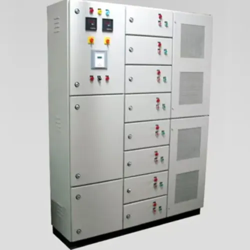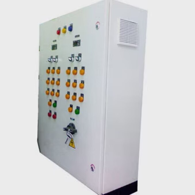
An MCC is not a single box filled with motor starters; it is an engineered assembly whose bus system, feeder units, protection, thermal design, and verification must work together. By the end, you will be able to trace a panel from the motor list and fault data to the final lineup, select the right starter for each load, and judge whether the completed assembly is suitable for operation and maintenance.
Key takeaways
- Start with the motor schedule and single-line diagram.
- Assign each motor a starter unit matched to its load and control method.
- Rate the incomer, bus, and units for load, fault current, heat, and expansion.
- Verify assembly safety, cooling, wiring, and fault coordination before commissioning.
How the motor list becomes an MCC lineup
The designer starts with the motor schedule and single-line diagram, not an empty cabinet. Each motor’s voltage, full-load current, starter type, protection, control signals, and cable entry becomes a unit; incomer and bus ratings follow the combined load, fault level, and expansion allowance.
- Group units by voltage, duty, process area, and access needs, then assign them to vertical sections.
- Route power through horizontal busbars and vertical busbars; place the incomer at the supply end, with feeder or starter units tapping the bus.
- Reserve cable chambers for power terminations and control compartments for relays, PLC I/O, terminals, and communications, then carry the arrangement into the general-arrangement drawing and schematic.
Construction choice changes the work after commissioning.
| Construction | Maintenance and wiring effect | Cost, rating, and spare-capacity effect |
|---|---|---|
| Fixed | Lowest wiring complexity, but isolation and replacement take longer | Lowest cost; verify fault rating for the complete assembly; provide spare ways |
| Removable | Unit can be disconnected and exchanged faster | More connectors and interlocks add cost and wiring; spare units need matching ratings |
| Withdrawable | Fastest routine replacement with shutters and mechanical interlocks | Highest cost and space demand; tested withdrawable construction determines fault performance |
An MCC organizes individual motor-control units. A PCC is primarily arranged around power distribution and larger feeders, not repeated starter buckets.
Select internal separation for the operating and maintenance objective. More barriers can protect adjacent circuits during work, but add space, heat-transfer resistance, joints, and cost; separation is not a universal quality score.
Centralized control also concentrates dependence on incoming power, control power, communications, and the bus system, so specify segregated supplies, spare capacity, and defined loss-of-communications behavior.
How each motor gets the right starter unit
1. Start with the motor schedule: match motor voltage and nameplate full-load current, then check process load, duty cycle, starting frequency, acceleration time, and speed-control requirement. A DOL starter suits a small, infrequently started motor whose supply can tolerate high inrush.
A star-delta starter reduces starting current when the motor has six accessible terminals and the load accepts reduced starting torque. Use a contactor feeder for simple switching, and a circuit-breaker feeder where isolation or non-motor distribution is the primary function.
2. Select a soft-starter feeder when reduced voltage stress and controlled acceleration are needed but running speed remains fixed. Select a VFD feeder when speed regulation, torque control, ramping, frequent starts, or energy control matters.
Confirm the drive’s input protection, specified bypass, separate control power, grounding and bonding, EMC measures, shielded motor-cable termination, heat dissipation, harmonics, and power-quality limits before choosing a conventional MCC starter bucket.
3. Keep the conventional bucket for compact across-the-line or reduced-voltage starters with ordinary cable routing and manageable heat. Use a drive panel or dedicated VFD section when the drive needs clearance, airflow, reactors, filters, bypass contactors, or segregated control wiring.
Do not substitute a VFD or soft-starter feeder into an existing bucket: its losses can overheat the enclosure, its switching can increase electromagnetic interference, its grounding and cable termination differ, and its harmonics can disturb the bus or sensitive loads. Recalculate overload settings, short-circuit protection, motor-cable length, thermal spacing, and control-power segregation before approval.
How protection, fault current, and heat set the ratings
Ratings start with motor full-load current, starting current, duty, ambient temperature, and prospective short-circuit current. The incomer and busbars carry the calculated demand, including diversity and starting voltage drop; outgoing feeders, contactors, and overload relays are sized for each motor’s nameplate current, acceleration time, starts per hour, and enclosure temperature.
Control transformers are sized from steady-state VA plus contactor pickup and other control inrush, then derated for ambient heat.
Keep these protection functions separate:
- Overload protection limits sustained overcurrent; its relay is selected around motor full-load current and starting behaviour.
- Short-circuit protection interrupts branch-circuit fault current. An overload relay is not this device.
- Earth-fault protection detects current returning outside the intended circuit.
- Phase-loss protection trips on missing or severely unbalanced phase voltage.
- Under-voltage protection prevents unsafe contactor re-energisation or motor operation.
- Motor thermal protection models winding heating, including duty cycle and repeated starts.
Obtain prospective short-circuit current from the utility, or calculate it from transformer kVA, secondary voltage, transformer impedance, and cable impedance; transformer fault current is approximately transformer full-load current divided by per-unit impedance, then reduced by downstream impedance.
Use that result to select device breaking capacity, busbar and assembly withstand, tested starter combinations, and coordination with the upstream protective device.
SCCR is an assembly-level rating: busbars, tap conductors, unit connections, contactors, overload devices, and verified combinations can limit it below the incomer breaker rating. Mark it against available fault current. SCCR alone does not predict arc-flash incident energy, which also depends on arcing current, enclosure, working distance, electrode orientation, and clearing time.
How the completed assembly is made safe, cool, and verifiable
Thermal design applies to the complete lineup, not to each starter in isolation. Heat review must include:
- Busbars, contactors, and overload relays
- VFDs, power supplies, and control transformers
Enclosure rating restricts ventilation; high ambient temperature reduces allowable current, while tight spacing traps heat. Route conductors to avoid blocking airflow, separate VFD heat from control equipment, and apply each manufacturer’s derating data. A drive substituted for a starter can force relocation or uprating.
Build a low-impedance protective path across doors, removable units, gland plates, barriers, cable armor, and protective conductors. Remove paint at bonding points where specified, use secure hardware, and verify continuity across every removable section; a loose bond can delay protective-device operation and disrupt EMC performance.
For assemblies built to UL practice, UL 845 addresses construction, wiring, dielectric withstand, temperature rise, short-circuit performance, and marking. IEC 61439-1 and IEC 61439-2 separate design verification from routine verification. A successful prototype test does not replace routine verification on each completed assembly.
The FAT should check:
- Approved drawings, nameplates, component part numbers, and torque records
- Protective-conductor continuity and applicable insulation or dielectric tests
- Interlocks, control logic, indication, local and remote operation
- Communications, simulated trips, and loss-of-communications fail-safe behavior
Record discrepancies against the delivered configuration, correct them, and retain the signed results with the assembly file.
How coordination determines what survives a fault
1. Type 1 coordination allows short-circuit damage that requires replacement before the motor starter returns to service. Type 2 coordination requires the tested starter and short-circuit protective-device combination to remain suitable for continued service, with limited damage permitted, such as contact welding that separates with light maintenance.
2. Some specifications distinguish partial Type 2, which allows that limited repair, from total Type 2, which requires no functional damage or replacement after the test. Confirm the governing edition of IEC 60947-4-1 and the project specification schedule before accepting either claim.
After a Type 1 fault, replace damaged contactors, overload devices, and other affected parts; after Type 2, inspect, test, and confirm contact condition, insulation, mechanisms, and protective operation before re-energising.
3. Do not substitute a breaker, contactor, or overload relay by rating alone. Coordination tables apply to a specific combination, and substitutions can invalidate motor starter coordination, the MCC’s assembly-level SCCR, and warranty or test evidence.
- Approved GA drawings and schematics
- Fault-rating basis and available short-circuit current
- Coordination tables for each starter combination
- Thermal assumptions and derating calculations
- Design and routine-verification records
- FAT results, including simulated trips and interlocks
- Clear identification of fixed, removable, and withdrawable units
Param Controls’ design and fabrication records become useful evidence when they show how those documents, ratings, and tests govern the delivered assembly—not merely that it is called reliable.
Related product
 | Electrical Control Panel Electrical MCC Panels - MCC Electrical Panel Motor Control Center Panels for Reliable Industrial Motor Management Param Controls manufactures and supplies MCC (Motor Control Center) Panels... View product → |
Frequently asked questions
How does a motor list become an MCC lineup?
The designer converts each motor’s voltage, full-load current, starter type, protection, control signals, and cable entry into an MCC unit, then arranges the units with the incomer, bus, and expansion allowance.
How do you choose the right starter unit for each motor?
Match the starter unit to the motor’s voltage, full-load current, starting method, protection requirements, and control signals.
What determines MCC panel ratings?
The combined load, available fault current, thermal conditions, and planned expansion determine the incomer, bus, and unit ratings.
How is a completed MCC assembly made safe and verifiable?
Check the enclosure, segregation, protective devices, cable entries, heat management, control wiring, labels, and test records before operation.
Why does coordination matter during a fault?
Coordination determines whether protective devices isolate the fault selectively and whether the affected starter unit and assembly withstand the fault without unnecessary shutdown or damage.