A repeated drive trip does not prove that the drive panel needs replacement. By tracing each alarm to the drive, motor, cable, supply, control circuit or mechanical load, then matching the replacement to measured site conditions, you can order a panel that solves the fault instead of reproducing it.
Key takeaways
- Record trip history, speed, load condition and incoming voltage before replacing a panel.
- Test the motor, cable, load and drive separately to locate the actual fault.
- Confirm motor data, drive rating and application duty before selecting a replacement.
- Specify protection, safety functions, drawings and acceptance tests in the order.
Match Each Trip to Its Actual Fault Source
Do not order a replacement panel from the alarm code alone. Record the trip history, operating speed, load condition and incoming voltage, then match each alarm with a physical check.
| Alarm | Likely source | Check before replacing the panel |
|---|---|---|
| overcurrent trip | Jammed load, acceleration time, motor fault or incorrect parameters | Inspect the machine, motor current and ramp settings |
| earth-fault trip | Damaged motor cable, wet motor, poor PE bonding or shield termination | Insulation-test the motor and cable with the drive disconnected |
| DC-bus overvoltage | Regeneration during stopping or an undersized brake resistor | Check stopping time, brake chopper and resistor power and energy ratings |
| DC-bus undervoltage | Supply sag, phase loss, loose terminals or undersized incoming protection | Measure line-to-line voltage during the trip |
| inverter overtemperature | Blocked airflow, high ambient temperature, switching frequency or cabinet heat | Check fans, filters, heatsinks and the thermal calculation |
| phase loss | Supply fuse, breaker, contactor or terminal failure | Measure all three phases at the drive input and output |
| output short circuit | Cable damage, motor winding fault or incorrect bypass switching | Test the motor and cable separately; verify bypass interlocking |
| motor overload | Excessive mechanical load or wrong motor data | Compare motor full-load current with actual current and drive settings |
| communication loss | Control wiring, shielding, address, network or PLC fault | Check cable continuity, termination and diagnostic logs |
For hoists, centrifuges, vertical conveyors and rapid-stop duties, confirm the braking method before blaming the drive. Regenerative energy exceeding the resistor or brake chopper causes a predictable DC-bus overvoltage.
Also inspect PE bonding, gland-plate and door bonding, cable shields and separation of motor, control, encoder and analog wiring; poor EMC practice can create repeated trips from a sound drive.
Separate Drive Failure from Motor, Cable and Load Problems
A trip code does not prove the drive is defective. Record the code, frequency, output current, DC-bus voltage and event time, then trace the circuit with power isolated and locked out.
- Check the incoming supply at the drive terminals. Measure all line-to-line voltages under load; a missing phase, voltage imbalance or loose termination can produce phase loss, undervoltage and repeated overcurrent trips.
- Inspect the motor cable, glands, shield and PE conductor. Test continuity and insulation resistance only after disconnecting the motor leads from the VFD; a megohmmeter connected through the drive can damage its output devices. Record each motor-cable result.
- Check the motor separately. Compare its full-load current with the drive setting, inspect terminal links and winding balance, and investigate motor overload when current remains high after the cable passes testing.
- Prove the drive output with the manufacturer’s approved disconnected-motor test or a known-good motor. An output short circuit that follows the drive points to its inverter section; a fault that follows the cable or motor does not.
- Test control wiring from the terminal to the PLC, selector or safety relay. A broken enable circuit, unstable 4–20 mA signal or false run command can mimic drive failure.
- Run the driven machine uncoupled where safe, then check bearings, alignment, blocked conveyors, pumps and gearboxes. Excessive torque explains overcurrent, braking faults and inverter overtemperature without condemning the panel.
Do not reset a recurring fault until you identify its source. A repeated phase loss or output short circuit needs correction, not a replacement order.
Check Motor Data, Drive Sizing and Application Duty
Motor kW alone cannot prove that a replacement drive is suitable. Compare the motor nameplate with the drive’s output-current rating and the real operating duty before accepting a quote.
1. Record the motor rated voltage, frequency, motor full-load current, rated speed, power factor, efficiency, duty type, insulation class and service factor. Size the drive by output current, not kW alone; a motor with high motor full-load current can exceed a drive’s capacity even when both nameplates show the same kW.
2. Identify the load classification. Constant-torque duty applies to conveyors, mixers, compressors and positive-displacement pumps, which need strong low-speed torque and higher overload capacity. Variable-torque duty suits centrifugal pumps and fans, where torque falls with speed. Selecting a variable-torque drive for a constant-torque load can cause acceleration trips and motor overheating.
3. Write down starts per hour, acceleration and deceleration times, minimum running speed, reversing frequency and whether the machine makes a high-inertia start. A large fan, centrifuge or loaded conveyor can exceed the drive’s short-time overload rating before reaching speed. Check the manufacturer’s overload class and duration against that start profile.
4. Check stopping energy before ordering. Hoists, vertical conveyors, centrifuges and rapid-stop machines may require a brake chopper and resistor sized for peak braking power and repeated-cycle energy. Excess regenerative energy causes predictable DC-bus overvoltage trips when the resistor or regeneration system is too small.
Also state ambient temperature, altitude, incoming voltage and frequency in the purchase specification; thermal derating can turn an apparently correct drive into an undersized one.
Verify Site Conditions, Protection and Installation Details
A replacement drive will not be reliable unless the panel matches the site’s fault level, heat, cabling and earthing. Record incoming voltage and frequency, ambient temperature, altitude, enclosure location, motor-cable length and prospective short-circuit current at the panel—not only the motor kW.
- Require the builder to state the assembly short-circuit withstand rating and coordinate it with the drive, busbars, terminals, enclosure and input protective device. A high-interrupting-capacity breaker alone does not rate the complete panel.
- Specify the fuse or breaker type, rating, trip curve, let-through energy and claimed Type 1 or Type 2 coordination. An unapproved MCB substitution can damage drive semiconductors or cause nuisance trips.
- Check PE continuity, gland-plate and door bonding, cable-shield termination, and separation between motor cables, control wiring, analog signals and encoder circuits. Poor EMC practice produces earth-fault, overcurrent and communication loss alarms.
- Select IP54/IP55 enclosure protection for the actual dust, moisture and washdown exposure. Confirm heat-loss calculations and ventilation; a sealed enclosure in a hot location can trigger inverter overtemperature.
- State the braking method, resistor resistance and wattage, duty cycle, mounting clearance and thermal protection. A braking-resistor fault can cause DC-bus overvoltage or fire if the resistor is incorrectly sized.
- If bypass exists, interlock contactors so line power cannot reach the motor while the drive is connected; specify stop, speed, phase-sequence, overload and restart logic.
| Item | Verify | Failure if missed |
|---|---|---|
| Cable | Length, shield and PE size | Reflected-wave or earth-fault trips |
| Earthing | Low-impedance protective bond | Shock risk and unstable feedback |
| Panel | Short-circuit withstand | Unsafe assembly during a fault |
Put the Required Tests, Drawings and Safety Functions in the Order
Make acceptance conditional on three deliverables: a complete purchase specification, a witnessed factory acceptance test and a handover dossier. A drive selected only by motor kW can fail on a high-inertia load, frequent starts, low-speed torque or high ambient temperature.
1. Purchase specification: state incoming voltage and frequency, motor full-load current, overload class, acceleration and deceleration times, duty cycle, ambient temperature, altitude, enclosure location, cable length, prospective short-circuit current and every required contactor. Name the fuse or breaker type, rating, trip curve, let-through energy and claimed Type 1 coordination or Type 2 coordination.
Require the complete panel assembly short-circuit withstand rating, not only the drive’s fault rating.
2. Safety definition: identify whether the stop is a control-panel stop command, drive inhibit, Safe Torque Off, emergency-stop contactor or incoming-power removal.
For a personnel hazard, specify the required Performance Level or SIL, dual-channel wiring, reset behaviour and proof-test interval; confirm that STO suits the hazard because it prevents torque production but does not remove hazardous voltage or stop a freely rotating load.
3. Factory acceptance test: witness phase-loss, overload, alarm, interlock, communication, braking and emergency-stop tests, plus parameter loading and protective-device operation. During commissioning, isolate and disconnect the motor before any megohmmeter test, then record motor-cable insulation results; testing through a connected VFD can damage its output devices.
4. Handover: demand a single-line diagram, schematics, terminal and cable schedules, gland list, heat-loss calculation, protection settings, revision-controlled nameplates, spare-parts list and drive parameter backup. Param Controls should provide these records with the panel, not leave undocumented changes for site troubleshooting.
Related product
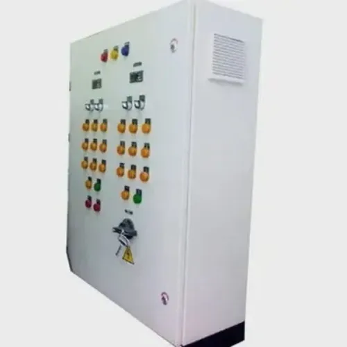
 | Electrical Control Panel Advanced Motor Speed Control & Industrial Automation Solutions Param Controls manufactures and supplies Drive Panels designed for reliable motor... View product → |
Frequently asked questions
How do you match a drive trip to its actual fault source?
Record the alarm code, trip history, operating speed, load condition and incoming voltage, then perform physical checks against the trip.
How can you tell whether the drive or motor is failing?
Separate checks of the drive, motor, motor cable and driven load help identify which part produces the fault.
What motor and drive details must you verify before ordering?
Check the motor nameplate data, drive sizing and application duty so the replacement suits the required operating conditions.
What site and installation details affect drive-panel reliability?
Verify incoming power, protection, installation conditions, wiring and required safety functions before finalising the panel.
What documents and tests should the panel order include?
Specify required functional tests, safety-function tests, drawings and other inspection records in the purchase order.