An MCC maintenance visit is only useful when it protects people, produces traceable readings and prevents repeat feeder failures. You will be able to plan inspection intervals, isolate equipment safely, evaluate service options in Nashik and decide when a fault belongs to the MCC, the motor, the drive or the wider process.
Key takeaways
- Inspect heat, odour, noise, vibration, trips and lamps every day.
- Isolate the MCC, test for absence of voltage and record evidence first.
- Compare thermal images with load current and previous fault history.
- Confirm parts, test results and safety documents before re-energizing.
Build a Maintenance Schedule Around Plant Conditions
Inspect the MCC daily for heat, burning odour, unusual noise, vibration, trip flags and failed indication lamps. Check that control power is present, ventilation openings are clear, and space heaters operate during humid shutdown periods.
- Daily: Walk the enclosure and record alarms, load indications, condensation, dust deposits and visible cable or door damage. Remove surface dust without opening the energized panel.
- Monthly: Perform an MCC enclosure inspection. Check door seals and gland plates, unused openings, drain or breather devices, latches, hinges and distorted sheet-metal doors. Confirm that replacement glands and gaskets preserve the intended IP rating.
- Quarterly: Review phase currents, switching frequency and fault history. Inspect contactors for chatter or welded contacts, overload relays for correct settings, molded-case circuit breakers for damage, fuses for heating or incorrect ratings, control transformers, lamps and space heaters. For withdrawable units, check stabs, shutters, racking mechanisms, interlocks and secondary disconnects.
- Annually: During a planned, safely isolated outage, inspect busbar joints and cable terminations for discoloration or looseness; test earth continuity and insulation resistance; verify breaker, overload and fuse ratings; and clean contamination from compartments.
A Nashik industrial plant maintenance plan must shorten these intervals after monsoon exposure, condensation, airborne dust, corrosive process chemicals, high loading or repeated faults. Record defects, readings, thermography images and corrective actions in the MCC preventive maintenance schedule so the next visit targets deterioration rather than repeating a visual tour.
Isolate the MCC and Record Evidence Before Testing
Schedule the outage, identify every incoming and backfeed source, and open the MCC incomer and relevant feeder disconnects. Apply MCC lockout tagout with personal locks and tags, then discharge capacitors and control transformers.
Perform proving dead with a correctly rated tester: test the tester on a known live source, check all phases to phase and earth, then retest the tester.
- Record the equipment ID, feeder or bucket number, isolation points, lock numbers, tester ID, date, and technician.
- Inspect withdrawable units for racking position, shutters, barriers, secondary disconnects, power stabs, disconnect-finger alignment, and contact pressure.
- Check busbar joints, cable lugs, gland plates, earth bonds, contactors, overload relays, and breaker terminals for looseness, heat damage, corrosion, or tracking.
- Do not perform MCC insulation resistance testing through drives, soft starters, surge suppressors, electronic trip units, PLC I/O, meters, power supplies, or communication modules; isolate them according to their manuals.
| Test | Record | What it proves |
|---|---|---|
| MCC insulation resistance testing | Voltage, test duration, phase-to-phase and phase-to-earth values | Insulation condition after sensitive devices are disconnected |
| earth continuity test | Test points, current or method, measured resistance, acceptance limit | Protective bonding from enclosure and doors to earth |
| Voltage and current check | Phase-to-phase voltage, each phase current, imbalance, load condition | Supply quality and load balance |
| Connection inspection | Torque values, stab condition, settings, defects, photos | Repeatable evidence of mechanical and electrical condition |
Attach the single-line diagram, thermographic images with load readings, breaker and overload settings, defect priorities, as-built changes, and obsolete or long-lead parts to the handover. Record any protection-setting change against the approved coordination study.
Use Thermography and Fault History to Find the Real Cause
A temperature alarm identifies where energy is accumulating, not why. Perform MCC thermography with the feeder carrying a documented, meaningful load, then compare each phase with its matching phase and like-for-like components; reflected infrared energy, unequal loading and changing demand can create false differences.
1. Record the feeder name, load current, phase balance, ambient conditions and temperature at terminals, busbar joints, breakers, contactors and cable lugs. A hot busbar connection points to loose torque, corrosion or contact resistance; it does not prove a motor fault.
2. Match the evidence to the trip record. An overload relay trip with rising motor current suggests mechanical loading, a failing motor or incorrect overload setting. A short circuit trip demands fault-current investigation, insulation checks and verification that the breaker’s interrupting rating suits available fault current.
3. Trace the feeder downstream. Check drive alarms, output current, acceleration data and motor terminals for a drive fault; check motor winding insulation, bearings and mechanical load for a motor fault. A cool feeder with a drive trip shifts suspicion to the drive or its control signals.
4. Test the control path: emergency-stop circuits, interlocks, PLC outputs, contactor coils, control fuses and loose terminals. Intermittent contacts after monsoon humidity, condensation, dust or process chemicals can mimic power faults.
5. Compare today’s readings with prior trips, temperatures, settings and repairs. Primary injection checks the complete feeder path, including conductors, CTs and trip chain; secondary injection checks the trip unit but cannot prove those primary connections.
Preserve the approved coordination study. A replacement with the same ampere rating can still change trip curves, overload class or instantaneous operation and create nuisance trips or unsafe selectivity.
Choose the Right Nashik Support Model and Service Scope
Compare MCC maintenance support Nashik providers by the failure you are preventing, the response time you need, and the records you will receive.
| Option | What it means | When it applies |
|---|---|---|
| Routine maintenance | Planned visual, torque, insulation, earth-continuity, contactor, overload, breaker and thermography checks | Use for scheduled work, with frequency based on load, dust, humidity, chemicals, switching duty and fault history |
| MCC emergency breakdown service | Fault finding, safe isolation, failed-component replacement and controlled restoration | Choose this for production stoppages; define arrival time, escalation and spare-parts access in advance |
| Remote troubleshooting | Guided review of alarms, measurements, photographs, drawings and settings | Use for control faults or nuisance trips that can be investigated without opening an energised MCC |
| annual maintenance contract MCC | Agreed visits, priority response, reporting, defect tracking and planned spares | Choose it when downtime is costly; ensure it includes condition-based adjustments, not one fixed annual visit |
| One-time inspection | A defined health check with findings and priorities | Use before an acquisition, after repeated trips, or to establish a baseline |
IEC 61439 sets assembly requirements, not one universal maintenance interval. For MIDC Ambad electrical maintenance, specify checks for monsoon condensation, airborne dust, corrosion and process chemicals; a harsh area may need shorter intervals than an office-like electrical room.
For withdrawable units, include stabs, pressure and alignment, shutters, racking, interlocks, secondary disconnects and barriers. Require thermography at documented load, plus settings, torque values, test readings, images, defect priorities and obsolete or long-lead parts. Ask Param Controls to define these deliverables before comparing prices.
Related product
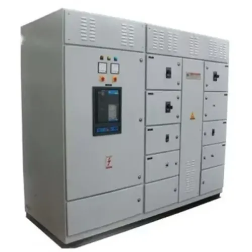
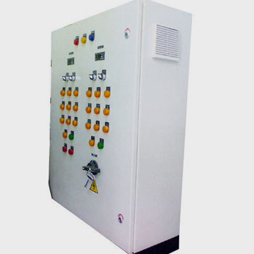 | Electrical Control Panel Electrical MCC Panels - MCC Electrical Panel Motor Control Center Panels for Reliable Industrial Motor Management Param Controls manufactures and supplies MCC (Motor Control Center) Panels... View product → |
Verify Parts, Standards and Handover Before Re-energizing
A return-to-service decision needs evidence, not a technician’s verbal assurance. File the latest single-line diagram, feeder and bucket identification, manufacturer instructions, approved settings, defect status, and every as-built change with the MCC maintenance records.
1. Confirm the assembly basis against IEC 61439-1 and IEC 61439-2. Check that replacement work preserves clearances, creepage distances, protective-circuit continuity, mechanical operation, dielectric performance and short-circuit withstand.
2. Apply MCC replacement breaker selection to the exact feeder. Match manufacturer and series, frame size, poles, voltage, interrupting rating, trip unit, trip settings, accessories, terminal arrangement and coordination study. A breaker that fits the compartment can still have the wrong fault rating or protection curve.
3. Inspect replacement glands, gaskets and gland plates for the enclosure’s intended IP rating. Seal unused openings, correct distorted doors, and verify that cable lugs, busbar joints and terminals receive the manufacturer’s specified torque. Record the component, torque value and calibrated tool.
4. Complete IEC 60364-6 verification: protective-conductor continuity, insulation resistance, polarity where applicable, functional operation and phase-to-phase voltage. Isolate drives, soft starters, surge suppressors, electronic trip units, power supplies, PLC I/O, meters and communication modules before megohmmeter testing.
5. Test each feeder’s breaker, contactor, overload relay, interlock, indication and emergency-stop function. Record insulation values, earth-continuity results, torque checks, thermographic images with load readings, and any failed item.
6. Before energizing, close covers, remove tools, clear personnel, cancel the work permit and remove locks only under the site’s authorized lockout procedure. Energize in stages, then record voltage, phase-current balance, alarms and abnormal heat; hand over the signed package, outstanding defects, obsolete parts and long-lead components.
Frequently asked questions
How should you schedule MCC panel maintenance around plant conditions?
Set inspection frequency according to load, dust, humidity, ambient heat, vibration, switching duty and the plant’s fault history. Daily visual checks should cover heat, burning odour, unusual noise, vibration, trip flags, indication lamps, control power, ventilation openings and space heaters.
What must you do before testing an MCC panel?
Isolate the MCC using the approved switching procedure, apply lockout and tagout, verify the isolation point, test for absence of voltage with a rated instrument and record the panel condition before removing covers or testing circuits.
How do thermography and fault history help diagnose MCC problems?
Use thermal images with load current, phase balance, connection condition and previous trip records. A hot termination, breaker or starter is evidence to investigate, not proof of one specific fault; compare readings under comparable operating loads.
What should you verify before re-energizing an MCC?
Check that replacement parts match the required ratings and dimensions, wiring and protective settings are documented, covers and barriers are fitted, tools are removed, test results are signed off and the handover records list outstanding work.