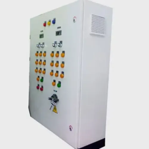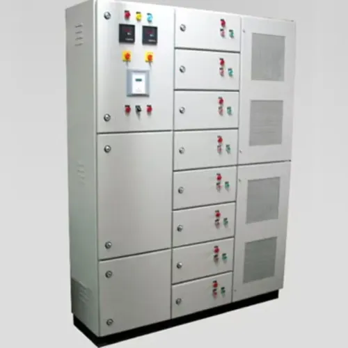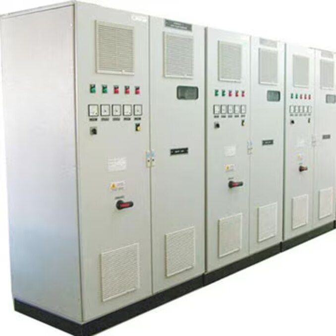
A quotation is only useful when every manufacturer prices the same electrical duty, physical arrangement, compliance evidence, and acceptance requirements. By defining the panel before requesting bids, you can compare engineering capability rather than choosing on price, component brands, or an attractive enclosure alone.
Key takeaways
- Give every manufacturer the same site load, fault-level and installation brief.
- Request design calculations, single-line diagrams, GA drawings and component schedules.
- Check protection coordination across utility, generator and alternate power sources.
- Compare busbar temperature rise, enclosure separation, fabrication controls and routine test records.
Define the PCC Panel Around the Actual Installation
Give PCC panel manufacturers a site-defined electrical and physical brief before requesting prices; otherwise each quotation may describe a different panel.
1. State the incoming voltage, frequency, phase arrangement, rated current, earthing system and expected diversity. Include transformer capacity, generator or solar sources, and whether a bus coupler or future incomer is required.
2. Provide the available fault current at the installation point, then specify the required short-circuit withstand rating. Ask manufacturers to state Icw, Ipk and any conditional short-circuit rating, coordinated with the upstream protective device. A high-rated incoming breaker alone does not establish the panel’s fault withstand.
3. Record the number of feeders or outgoing feeders for PCC panel manufacturers comparison. Identify each feeder’s load, voltage, starting method, protective device, cable size and spare capacity.
4. Define the busbar arrangement, neutral and earth bars, compartmentalisation or form of separation, enclosure material, IP rating, ventilation and arc-flash performance requirement. Request evidence for the actual construction; IEC TR 61641 results do not automatically transfer to another enclosure, busbar layout or pressure-relief design.
5. Draw the installation boundary: indoor or outdoor location, ambient temperature, altitude, cable-entry direction, gland-plate position, maintenance access and available floor or wall space. Thermal performance changes with enclosure dimensions, simultaneous loading, ventilation and temperature.
6. Identify the required product basis before comparison: IEC 61439-1 and IEC 61439-2 for low-voltage assemblies, UL 891 for switchboards, UL 845 for motor-control centres, or UL 508A for industrial control panels. Ask for the matching design-verification evidence, not a component list.
Demand Design Verification and Complete Technical Documents
A compliant PCC proposal needs design verification to IEC 61439-1 and IEC 61439-2, not a component list or an old “type-tested” label. Ask the manufacturer to identify whether each characteristic was verified by test, calculation or measurement, or comparison with a verified reference design.
Request these documents for the proposed assembly:
- A single-line diagram (SLD) for PCC panel selection checklist, showing incomers, bus couplers, feeders, ratings and protection devices.
- General-arrangement and enclosure drawings showing dimensions, cable entries, busbar routes, internal separation and access.
- A bill of materials, control schematics and datasheets for ACBs, MCCBs, fuses, relays, meters and surge protection.
- Design-verification evidence covering temperature rise, short-circuit withstand, clearances, creepage distances and protective-circuit effectiveness.
- Routine-verification records for the actual panel, including enclosure protection, wiring, component incorporation, operational performance, dielectric properties and protective-circuit continuity.
Heat evidence must match your installation. Check simultaneous loading, diversity, busbar layout, enclosure size, ventilation, ambient temperature and altitude; a ventilated reference arrangement does not prove performance for a dense outdoor panel.
For North American projects, confirm the product category rather than accepting a generic UL claim:
| Standard | Assembly covered | Evidence to request |
|---|---|---|
| IEC 61439-1 and IEC 61439-2 | Low-voltage power switchgear assembly | Assembly design and routine verification |
| UL 891 | Switchboard or PCC | Evaluation to UL 891 |
| UL 845 | Motor-control center | Evaluation to UL 845 |
| UL 508A | Industrial control panel | Panel evaluation; Supplement SB SCCR is not a substitute for UL 891 or UL 845 where those apply |
Test Protection Coordination Against Every Power Source
A manufacturer has proven fault-level competence only when its short-circuit calculation starts at the installation point and includes every source: the utility transformer, generator, bus coupler and alternate incomer. Request the maximum available fault current, protective-device time-current curves, trip settings and discrimination study for each operating configuration.
Check that the panel rating matches all of these values:
- Available fault current at the bus
- Rated short-time withstand current, Icw
- Rated peak withstand current, Ipk
- Conditional short-circuit rating with the specified upstream device
A high-rated incoming breaker does not establish a high panel rating. The lowest-rated power-circuit component, busbar assembly and any device combination dependent on an upstream fuse or breaker can limit the result.
For North American projects, request an SCCR calculation for PCC panel manufacturer evaluation and identify whether the assembly falls under UL 891, UL 845 or UL 508A. UL 508A Supplement SB procedures do not replace the construction and product requirements for a complete switchboard or motor-control-center assembly.
For IEC projects, ask for IEC 61439-1 and IEC 61439-2 design-verification evidence for the actual assembly system, including short-circuit withstand and protective-circuit effectiveness. Confirm that the manufacturer has coordinated ACB, MCCB and fuse settings against upstream protection, rather than selecting each device independently.
Reject generic certificates that do not state the tested construction, fault level, upstream device and bus arrangement.
Compare Busbars, Separation, Enclosure and Thermal Design
Busbar material and sizing must match the incoming current, fault level, temperature-rise design and installation altitude. Ask for the rated short-time withstand current (Icw), peak withstand current (Ipk) and conditional short-circuit rating at the installation point, not only the incoming breaker’s interrupting rating.
Confirm the upstream device that limits the fault and request evidence for that exact assembly.
Form of separation changes what an operator can reach while another circuit remains energised. Compare the options directly:
| Form of separation | Access and serviceability | Trade-off |
|---|---|---|
| Form 1 | Busbars, functional units and terminals share the enclosure | Lowest cost, least isolation |
| Form 2 | Busbars are separated from functional units | Safer feeder access, limited terminal isolation |
| Form 3 | Busbars and each functional unit are separated | Better maintenance access, more space and cost |
| Form 4 | Busbars, functional units and associated terminals are separated | Highest segregation, largest footprint and cost |
Specify clearance and creepage distances for the rated voltage, pollution level and altitude; cramped terminals invite tracking, flashover and unsafe maintenance. A stated form does not prove internal arc containment, so request IEC TR 61641 evidence for the actual construction if arc performance matters.
Treat heat dissipation as a design input. Require temperature-rise verification based on simultaneous loading, diversity, busbar arrangement, enclosure dimensions, ventilation, ambient temperature and altitude. Confirm the final IP54 or IP55 enclosure rating after doors, gland plates, cable entries, filters, louvers and field modifications are installed.
Obtain routine-verification records for every production panel, including enclosure protection, protective-circuit continuity, wiring, operation and dielectric properties.
Audit Fabrication Quality, Testing and Acceptance Controls
Compare production capability by asking for records from the same type of PCC assembly, not a generic ISO 9001 certificate. The acceptance plan must link each critical feature to a measurable record and a person responsible for approval.
| Capability area | Evidence to request | Acceptance check |
|---|---|---|
| Sheet-metal fabrication | Sheet-steel thickness certificates, drawing tolerances, first-article dimensional report, and revision-controlled bend tooling | Verify hole position, door alignment, mounting-plate flatness, and interchangeability across batches |
| Welding and lifting parts | ISO 3834 welding quality system, approved weld procedure, welder qualifications, inspection level, and acceptance standard | Inspect welds against the specified criteria; ISO 3834 certification alone does not qualify your weld design |
| Painting or powder coating | ISO 12944 coating system matched to the site corrosivity category, surface-preparation record, coating thickness, cure, adhesion, and repair procedure | Check edge and weld coverage, adhesion, cured finish, and documented repairs |
| Assembly testing | IEC 61439-1 and IEC 61439-2 design-verification evidence for the actual assembly system | Require routine verification for dielectric withstand, protective-circuit continuity, wiring, polarity, operation, and clearances |
Put hold points before painting, wiring closure, and dispatch. Require photographs, calibrated-instrument records, signed inspection sheets, and the final as-built drawings with serial numbers.
Param Controls should be evaluated on whether its factory can produce these records consistently, not on a certificate displayed in the quotation. Reject a panel with unexplained substitutions, missing test values, or dimensions accepted only by visual inspection. Salt-spray hours alone do not prove outdoor life; assess the complete ISO 12944 system and exposure.
Related product
 | Electrical Control Panel PCC Panel - PPC Electrical Panel Power Control Center Panels for Reliable Industrial Power Management Param Controls manufactures and supplies PCC (Power Control Center) Panels... View product → |
Frequently asked questions
What site information should you give a PCC panel manufacturer before requesting prices?
Provide the supply voltage and frequency, incoming fault level, transformer and generator ratings, connected and maximum demand loads, number of incomers and outgoing feeders, short-circuit withstand requirement, installation altitude, ambient temperature, indoor or outdoor location, cable-entry direction, dimensions, IP rating and maintenance clearances.
Which technical documents should you request from a PCC panel manufacturer?
Request the single-line diagram, general-arrangement drawing, power and control schematics, bill of materials, component datasheets, busbar sizing and temperature-rise calculations, short-circuit withstand evidence, protection settings, cable schedule, terminal plan, foundation details and inspection and test plan.
How do you check PCC protection coordination across multiple power sources?
Review time-current curves and settings for utility incomers, generator incomers, bus couplers, ACBs, MCCBs and downstream devices. Check fault cases for utility supply, generator supply, parallel operation and bus-coupler transfer so the nearest protective device trips first without losing healthy sections.
What should you compare in PCC busbars, enclosure and thermal design?
Compare copper or aluminium busbar material, current density, short-time and peak withstand ratings, neutral and earth-bar sizing, temperature-rise limits, form of internal separation, enclosure IP rating, ventilation, cable-compartment space and access for torque checks and maintenance.
Which fabrication and acceptance controls matter before PCC panel delivery?
Check material traceability, enclosure dimensional inspection, bar joint preparation and torque records, wiring ferrule and terminal identification, protective-earth continuity, insulation resistance, dielectric withstand, mechanical operation, interlock checks, functional tests and signed routine-test reports.