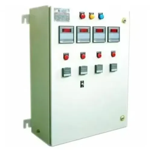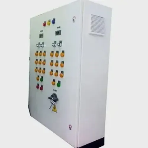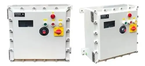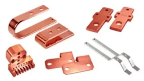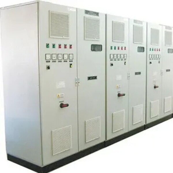
A failed PCC panel demands more than a quick breaker change: hidden arc damage, weakened busbar joints, obsolete protection parts, and environmental exposure can make a seemingly cheap repair unsafe. You will be able to triage the failure, choose between component repair and complete replacement, compare the real project impacts, and define the tests and records required before energization.
Key takeaways
- Isolate and discharge the panel before opening covers or testing circuits.
- Inspect busbar supports, shrouds, barriers, and cable terminations after a fault.
- Choose repair only when insulation, mechanical strength, and protection remain dependable.
- Record insulation, continuity, interlock, and protection tests before re-energizing.
What should you check first after a PCC panel failure?
Do not recommend repair or replacement until the panel is safe and the failed circuit is identified. A high-fault event can damage hidden barriers, busbar supports, shrouds, and cable terminations; intact covers do not define the repair boundary.
1. Isolate the incoming supply and apply electrical panel lockout tagout. Prove dead with an approved tester at the incomer, busbars, and affected feeder, then verify the tester on a known live source. Record alarms, trip indications, breaker position, and the affected incomer or feeder.
2. Photograph the panel before opening or moving anything. During PCC panel fault diagnosis, look for arc marks, carbonized insulation, melted barriers, loose or discolored joints, damaged cable terminations, cracked supports, and displaced shrouds. Identify the failed breaker, relay, contactor, control fuse, termination, or protection device.
3. Test protective-conductor continuity and record the insulation resistance test PCC panel results for relevant conductors, phases, and earth. Inspect busbar joints for oxidation, heat damage, distorted hardware, lost spring pressure, or annealed copper or aluminium; restoring torque alone does not repair damaged metal or brittle insulation.
4. Treat every high-fault event as potentially deeper than its visible marks. Extend the inspection behind covers and into supports, barriers, cable bends, and adjacent compartments before defining the repair boundary. Complete functional checks only after the fault cause is isolated and the equipment remains safely de-energized.
This evidence completes the PCC panel trip investigation and supports a defensible repair decision.
When is PCC panel repair safer and more practical than replacement?
Repair is safer and more practical when industrial panel failure assessment finds a local defect and confirms that the enclosure, busbar system, barriers, incoming device, and protection platform remain sound.
A failed contactor, relay, indication lamp, cooling fan, control fuse, cable lug, or replaceable feeder device does not by itself justify PCC panel repair or replacement.
| Option | Choose it when | Main warning |
|---|---|---|
| Repair | The panel is structurally sound, relatively young, has no repeated fault history, and certified spares are available | A low-cost repair can preserve an obsolete protection platform |
| Replace affected section | A busbar joint, feeder device, barrier, or termination has heat or fault damage | Annealed metal, damaged plating, brittle insulation, or distorted hardware needs more than retightening |
| Replace complete assembly | Carbonized insulation, distorted or annealed busbars, cracked insulators, severe PCC enclosure corrosion, recurring fault damage, or unavailable certified trip units and auxiliaries are present | Altered protection, cooling, separation, or connections can require IEC 61439 design-verification reassessment |
Do not assume Nashik industrial electrical conditions from the site address. Record dust deposits, heat, humidity, chemical exposure, vibration, and monsoon moisture, then inspect door seals, ventilation, gland plates, unused cable-entry holes, and bonding. A repaired enclosure retains its IP designation only when the completed arrangement preserves that protection.
Replacement becomes the safer choice when the panel’s age, fault history, spare-part availability, or compliance risk makes future failure unpredictable. Revisit arc-flash assessment after changing a breaker, busbar, transformer, or feeder; incident energy depends on fault current, clearing time, settings, enclosure configuration, and working distance.
When does a component repair become a complete PCC assembly replacement?
A component repair replaces a defined part inside a sound assembly; a complete PCC assembly replacement is required when the enclosure, busbar system, connections, or protection architecture can no longer be verified as safe and compliant.
A circuit breaker replacement must satisfy circuit breaker replacement requirements for operational voltage, Icu, Ics where specified, frame and connection geometry, pole configuration, insulation voltage, trip-unit characteristics, and coordination with upstream and downstream devices. The same frame size is not enough. Check:
- Replace only the breaker when the enclosure, PCC busbar arrangement, withdrawable mechanism, incoming device, metering, ventilation, and internal separation remain undamaged and compatible.
- Replace the assembly when fault forces have distorted busbars, cracked supports, damaged the incoming device, or made the withdrawable mechanism unreliable.
- Reject component-only work when a new trip unit, current-transformer ratio, or feeder device destroys selectivity or changes instantaneous, short-time, or earth-fault protection.
- Treat a PCC busbar replacement, altered short-circuit protection, enclosure, cooling system, internal separation, or connection as a possible IEC 61439 PCC panel design change requiring PCC design verification reassessment, not routine testing alone.
Sheet-metal or gland-plate changes can reduce creepage, clearance, cable-bending space, protective bonding, or IP performance. Paint is not an earth path; seal unused entries and verify bonding across coated joints. If these defects cannot be demonstrated against the original design, replace the complete PCC assembly rather than preserve a compromised enclosure.
How should you compare repair and replacement for a Nashik plant?
Compare repair and replacement on total plant impact, not purchase price alone. Use this PCC panel replacement cost comparison worksheet:
| Option | Repair | Replacement |
|---|---|---|
| Downtime and temporary power | Shorter outage; confirm bypass or generator capacity | Longer outage; price temporary distribution and changeover work |
| Engineering and lead time | Check compatibility and obsolete parts | Allow design, fabrication, procurement, and delivery |
| Testing and installation | Test the affected section and interfaces | Test the complete assembly; remove, install, terminate, and commission |
| Lifecycle reliability | Confirm certified spares, calibration, and service support | Confirm platform life, future spares, and maintainability |
For PCC panel downtime planning, ask each bidder to state outage hours, temporary-power assumptions, site labour, testing scope, and exclusions. Compare installation access, cable retermination, shutdown sequencing, and the consequences of a failed spare.
Send this evidence before requesting a quotation:
- Single-line diagram, panel nameplate, incomer and feeder ratings, prospective fault level, protection settings, and load list
- Photographs, trip history, panel drawings, cable details, and available short-circuit data
A major repair or replacement section can alter protection selectivity PCC panel performance, earth-fault operation, instantaneous pickup, and short-time delay. Recalculate settings against actual fault and feeder data, then complete an arc-flash assessment industrial panel review because clearing time, enclosure configuration, working distance, and incident energy can change.
Ask Param Controls, other qualified panel manufacturers, or repair specialists to define scope, design responsibility, temporary-power assumptions, test documents, and future-spares support.
Related product
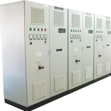 | Electrical Control Panel PCC Panel - PPC Electrical Panel Power Control Center Panels for Reliable Industrial Power Management Param Controls manufactures and supplies PCC (Power Control Center) Panels... View product → |
What tests and records must be completed before re-energizing?
Do not re-energize until the repaired or replaced assembly passes a documented acceptance decision, not merely a visual inspection. Complete PCC panel testing and commissioning in this order:
1. Verify every busbar, terminal, and cable connection against the torque schedule, recording the tool reading and applied value. Perform PCC insulation resistance testing, a protective earth continuity test, conductor continuity, phase identification, and phase-sequence verification.
2. Record each breaker and relay setting, including pickup, time delay, and instantaneous functions. Check control-circuit fuses, coils, remote commands, auxiliary contacts, functional interlocks, alarms, meters, lamps, and other indications.
3. Prove protective-device operation using the specified primary or secondary injection test, trip test, or manufacturer-approved functional method. A megohmmeter detects leakage; it cannot prove short-circuit withstand or the mechanical and thermal strength of the busbar system. Specify power-frequency withstand testing when the incident, design change, or assembly manufacturer requires it.
4. Use thermal imaging only as a loaded follow-up check on joints. Match the load, phase balance, emissivity, camera position, and enclosure airflow with any comparison scan; investigate a hot joint by de-energized inspection and joint rework, not by simply tightening it.
5. Before controlled energization, inspect covers, shrouds, barriers, gland seals, unused entries, cable stress, and bonding across coated metalwork. Close the PCC panel acceptance documentation with as-built drawings, busbar and cable identification, all test values, settings, interlock results, and applicable IEC 61439 design-verification and routine-verification evidence.
Frequently asked questions
What should you check first after a PCC panel failure?
Isolate all incoming and backfeed sources, apply lockout and tagout, verify absence of voltage, and identify the failed circuit. Inspect busbars, supports, shrouds, barriers, breaker compartments, cable lugs, and signs of arcing or heat damage.
When is PCC panel repair safer than replacement?
Repair is safer when the fault is limited to a replaceable component and the enclosure, busbar system, insulation, supports, clearances, and cable terminations pass inspection and testing.
When does a component repair become a complete PCC assembly replacement?
Replace the assembly when heat, arcing, contamination, or mechanical distortion affects busbars, insulation barriers, supports, compartments, or multiple outgoing circuits, or when safe clearances and protection coordination cannot be verified.
How should you compare repair and replacement for a Nashik plant?
Compare outage duration, spare and fabrication lead time, fault damage, service continuity, protection compatibility, test requirements, future load, and the cost of repeat failure rather than comparing component prices alone.
What tests and records must be completed before re-energizing?
Complete visual inspection, protective-earth continuity, insulation-resistance testing, phase identification, breaker operation, interlock checks, and primary or secondary injection tests where protection settings require them. Record test values, instruments, settings, replaced parts, torque checks, and approval to energize.