An organized distribution system starts with a defined path: incoming supply, main incomer, busbars, outgoing feeders, and final loads. By the end, you will know how to choose the panel architecture, specify its electrical inputs, assign protection, and request the drawings and verification records needed to keep the installation traceable and serviceable.
Key takeaways
- Map the power path from the incomer through busbars to every load.
- Match panel architecture to load ratings, process layout, and maintenance access.
- Collect fault level, load, enclosure, and environmental data before sizing.
- Demand traceable wiring, verified protection, accurate drawings, and serviceable fabrication.
Trace the Power Path from the Incoming Supply to Each Load
The incoming supply enters the panel through the main incomer, which provides the primary isolation and protection point. From there, power passes to the busbars, where conductors distribute it across the assembly without forcing every circuit through one terminal path.
A single-line diagram shows this route clearly, from the source and incomer to each protective device, cable run, isolator, and final load.
Outgoing feeders like these carry power beyond the panel:
- Production lines
- Lighting
- HVAC
- Utilities
- Fire systems
- Critical loads
Each labelled feeder should identify its destination, protective-device rating, cable route, and supply source. At the receiving end, a local isolator, distribution board, motor starter, or machine panel controls the circuit before it reaches the final loads. This arrangement lets a technician isolate one process without shutting down unrelated equipment.
The physical layout must support the diagram. Separate power and control wiring with barriers, wireways, and terminal blocks; preserve conductor bending space; and keep field terminations away from live sections. Provide the working clearance required by NEC 110.26 around the installed equipment, not just space inside the enclosure.
A neat panel that blocks breaker access or forces cables across energized parts is not organized distribution. Trace every feeder from its label to the load, then confirm the installed path matches the drawing.
Choose the Panel Architecture Around the Load and Process Layout
Select the architecture by load type, motor concentration, process layout, and required centralisation. A single enclosure is not automatically the most organized solution.
| Option | What it means | When it applies |
|---|---|---|
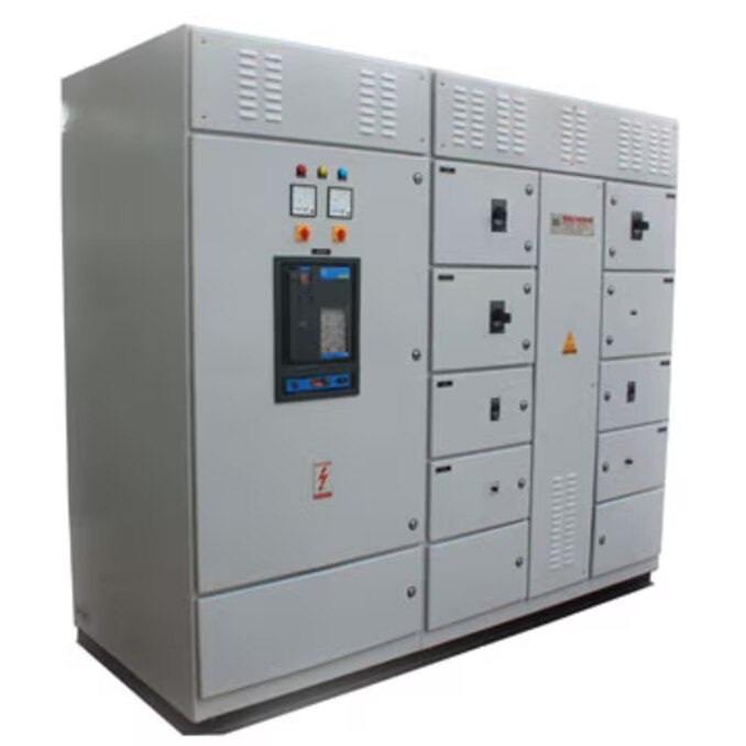
| Power Distribution Panel | Main low-voltage distribution point with incomer, busbars, and outgoing feeders | Mixed motor loads and non-motor loads require centralized distribution |
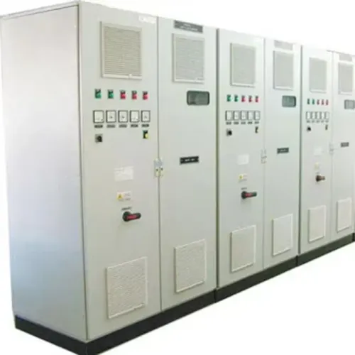
| PCC | High-capacity central panel feeding major plant sections or large downstream assemblies | Use one incomer and multiple high-rated feeders at a common location |
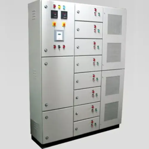
| MCC | Motor control centre with starters, contactors, overloads, and drives | Motor concentration is high and operators need grouped motor control |
| Separate feeder panels | Downstream panels serving defined areas or process zones | The process layout spreads loads across buildings, floors, or production lines |
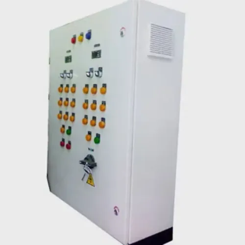
| Machine panels | Local control and power enclosure for one machine or skid | Machine isolation, local troubleshooting, and OEM control wiring matter |
Use a PCC or Power Distribution Panel when short cable routes, centralized protection, and a single maintenance point outweigh the cost of longer feeder runs. Add separate feeder panels when distance, process zoning, or phased expansion would otherwise fill the main enclosure with crowded terminations.
Choose an MCC for grouped motors, not simply because one motor exists. Put controls and final isolation in machine panels when operators must shut down one machine without taking an entire line offline.
Check continuous loads before fixing feeder ratings: NEC 215.2 and 215.3 apply 125 percent of continuous load plus noncontinuous load. Confirm whether the assembly is a UL 67 panelboard, UL 891 dead-front switchboard, or UL 508A industrial control panel.
Collect the Design Inputs Before Sizing the Assembly
Do not size the incomer from connected load alone: a 400 A total can produce a different requirement after maximum demand, diversity factor, continuous load, and future expansion allowance are applied. Record the supply voltage, phase, frequency, prospective short-circuit current, and available fault current at the panel terminals.
| Input | Sizing consequence | Required check |
|---|---|---|
| Load calculation | Sets incomer, feeders, cables, and device ampere ratings | Apply NEC 215.2 and NEC 215.3: noncontinuous load plus 125% of continuous load |
| Fault duty | Sets busbar withstand and protective-device interrupting rating | The interrupting rating must meet available fault current |
| System data | Sets breaker and cable voltage rating, poles, and frequency suitability | Match every device to the system |
| Thermal conditions | Limits busbar and conductor ampacity | Check enclosure heat dissipation, grouping, connections, insulation, and busbar temperature rise |
Provide feeder-by-feeder load details, motor starting current, cable lengths, installation method, ambient temperature, and allowable voltage drop. A long cable run can require a larger conductor even when its ampacity passes.
Then confirm the assembly’s short-circuit withstand and marked SCCR under the selected construction standard. IEC 61439 design verification covers temperature rise, dielectric performance, short-circuit withstand, and protective-circuit effectiveness; a breaker’s individual rating does not prove the completed assembly.
Use the lowest applicable component or approved combination rating, and leave spare capacity only after the expansion allowance is stated.
Build Protection, Isolation, and Wiring That You Can Trace
Place the main ACB at the incoming supply, then feed busbars and outgoing feeders in a direction that matches the single-line diagram. Give each feeder its own MCCB or MCB, with ratings and settings selected for short-circuit protection and overload protection, not merely normal load current.
Reserve a lockable device for isolation; a breaker that trips is not automatically a safe isolator. Confirm the panel SCCR against the weakest power component or a documented combination, such as a UL 508A Supplement SB pairing or current-limiting fuse arrangement.
- A motor circuit uses a motor protection circuit breaker for short-circuit and overload protection, then a contactor and overload relay where remote starting and motor overload response are required.
- A general final circuit uses an MCB or fuse sized for the conductor and load, with coordination that prevents a downstream fault from needlessly tripping the incomer.
- Add residual-current protection, earth-fault protection, and surge protection where the installation risk and equipment require them.
Keep live power sections separate from control and communication wiring. Terminal blocks, wireways, barriers, and segregation preserve bending radius, prevent accidental contact, and leave access for testing and replacement. Use shrouding around exposed conductors, interlocking where an unsafe operating sequence is possible, and clear labels to reduce arc-flash risk. Provide earthing and protective bonding throughout.
Maintain the dedicated working space specified by NEC 110.26, and apply NFPA 79 to machine disconnects, grounding, conductor identification, and machine overcurrent protection.
Require Assembly-Level Verification, Drawings, and Serviceable Fabrication
Before delivery, require the manufacturer to prove the panel as an assembled system, not by handing over breaker datasheets. Ask for these records and inspection points:
1. Request IEC 61439 design verification where IEC practice applies, including temperature rise, dielectric performance, short-circuit withstand, and protective-circuit effectiveness. Confirm the marked SCCR against NEC Article 409. For North American work, identify whether construction follows UL 508A, UL 67, or UL 891, and request UL 508A Supplement SB evidence for the SCCR method.
Check NEMA 250 enclosure type and the stated IP rating against the installation environment.
2. Approve the document pack: general-arrangement drawing, schematic drawing, single-line diagram, cable schedule, and component schedule. The drawings must show access clearances, terminal numbers, feeder identities, gland plates, and bonding jumpers; otherwise installation changes become guesswork.
3. Require routine verification records and test reports covering visual and mechanical inspection, conductor identification, protective-bond continuity, insulation test, dielectric test, and functional test. A successful power-up does not prove dielectric strength or a continuous protective path.
4. Inspect serviceability before dispatch. Specify sheet-metal tolerances, door alignment, gasket compression, component clearances, gland-plate fit, and bonding points; painted metal contact alone is not proof of continuity.
Param Controls can support this evidence-led handover when its fabrication package defines inspection points rather than relying on nominal CAD dimensions.
Related products
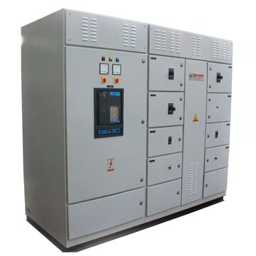 | Electrical Control Panel Reliable & Efficient Electrical Power Distribution Solutions Param Controls manufactures and supplies Power Distribution Panels designed for the... View product → |
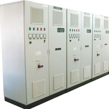 | Electrical Control Panel PCC Panel - PPC Electrical Panel Power Control Center Panels for Reliable Industrial Power Management Param Controls manufactures and supplies PCC (Power Control Center) Panels... View product → |
Frequently asked questions
How does power move through a distribution panel?
The incoming supply reaches the main incomer for isolation and protection, then flows to busbars and outgoing feeders serving individual loads.
What design inputs are needed before sizing a distribution panel?
Collect supply voltage, frequency, connected and demand loads, fault level, feeder requirements, enclosure conditions, cable entries, and process layout.
What should assembly-level verification cover?
Verify protection settings, isolation, busbar and cable connections, wiring identification, enclosure fabrication, drawings, and access for inspection and maintenance.
Related product
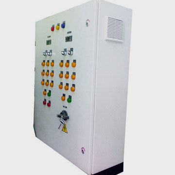 | Electrical Control Panel Electrical MCC Panels - MCC Electrical Panel Motor Control Center Panels for Reliable Industrial Motor Management Param Controls manufactures and supplies MCC (Motor Control Center) Panels... View product → |