A bus bar rated only by its copper cross-section can overheat at a joint, fail under fault forces, or violate clearance requirements inside the finished panel. By working through load, environment, fault duty, insulation distances, material, and construction choices, you can produce a specification that a manufacturer can calculate, build, and verify.
Key takeaways
- Start with continuous current and allowable temperature rise.
- Increase the copper section for heat, grouping, and enclosure conditions.
- Specify copper grade, plating, joints, and conductor construction.
- Check fault forces, clearances, creepage, and support spacing.
Start with continuous current, temperature rise, and the actual installation
Start with the load, not the bar dimensions. A copper bus bar’s continuous current rating is the maximum current it can carry continuously without exceeding the allowable temperature rise in the completed assembly.
Calculate the highest simultaneous load at the design duty cycle, then account for harmonics and planned capacity; do not add nameplate currents that cannot operate together.
Record these inputs before selecting the copper bus bar cross-sectional area:
- Design current, system voltage, frequency, duty cycle, and ambient temperature.
- Enclosure dimensions, ventilation openings, altitude, and the temperature ratings of terminals and adjacent insulation.
- Bar orientation, spacing between phases, proximity to heat sources, surface finish, and the number of energized bars grouped together.
- Available width, thickness, bend locations, connection hardware, and required temperature-rise limit.
Width and thickness ampacity are not interchangeable. A wide, thin bar exposes more surface for cooling, while a thick bar can behave differently inside a tight enclosure; the same cross-sectional area can receive different ratings after heat transfer and terminal limits are considered.
| Installation condition | Consequence for sizing | Check before approval |
|---|---|---|
| Open, ventilated enclosure | Heat escapes more readily | Confirm airflow and ambient temperature |
| Tight, unventilated enclosure | Copper runs hotter | Reduce allowable current or increase copper and spacing |
| Grouped phase bars near heat sources | Mutual heating raises temperature | Evaluate the complete arrangement |
| Laminated flexible connection | Movement is easier to accommodate | Verify its continuous rating and restraint separately |
Validate the result by temperature-rise testing or the applicable assembly design-verification method, not by area alone.
Adjust the copper section for heat, grouping, and enclosure conditions
The same copper cross-section can carry different continuous current in different panels. Rate it against the allowable temperature rise of the complete assembly, including the enclosure, insulation, terminals, and nearby heat sources—not copper area alone.
Record these thermal inputs before fixing the section:
- Measure enclosure temperature and ambient temperature at the bus location, not only room temperature.
- State whether ventilation is natural, filtered, forced-air, or sealed; restricted airflow raises conductor temperature.
- Apply altitude derating when reduced air density limits convection or dielectric clearance.
- Include heat from a relay, breaker, or other device mounted beside the bar.
- Define duty cycle and grouping; intermittent loading can produce a different thermal result from continuous loading, while grouped bars retain heat.
- Check proximity to energized conductors, phase spacing, and other hot components.
For a given copper area, a wider, thinner bar usually dissipates heat better than a narrow, thick bar because it exposes more surface. Thickness still affects mechanical strength, voltage drop, fault forces, and available hole area.
Increase width or thickness when the calculated temperature rise is too high; add parallel bars when space, current sharing, and termination hardware permit it. Leave clear air gaps between parallel bars rather than stacking them tightly.
Set bar orientation deliberately: a vertical face often improves natural convection, while a horizontal stack can trap heat. Confirm parallel bars have equal lengths, matched joints, and enough spacing for airflow; otherwise one bar can run hotter and carry disproportionate current.
Specify copper grade, joints, plating, and the right conductor construction
Choose C11000 electrolytic tough-pitch copper for a standard conductive bus bar, then confirm its temper against forming and fault-force needs. Oxygen-free copper is not an automatic upgrade: compare copper temper conductivity, mechanical strength, brazing or welding requirements, and forming springback before substituting it. Hard temper resists deformation but demands greater forming force.
| Option | Best fit | Main trade-off |
|---|---|---|
| Solid copper bar | Rigid, braced connections with predictable heat dissipation | Transmits vibration and needs accurate alignment |
| Laminated flexible bus bar | Movement, vibration, or tight alignment between fixed terminals | Needs separate short-circuit restraint and thermal verification |
| Cable | Long routes, frequent movement, or flexible termination | Larger bending space and different lug and insulation requirements |
| Aluminum bar | Weight or material-cost reduction after interface review | Requires oxidation control, larger section, and compatible joint hardware |
| Parallel copper bars | High current or a geometry that cannot fit one bar | Needs equal-length paths, spacing, and balanced connections |
Specify tin plating for a practical oxidation-resistant contact surface; use silver plating when contact resistance and elevated-temperature performance justify the cost. State plated faces, minimum coating thickness or standard, and treatment of cut edges and drilled holes.
Treat every bolted joint as a thermal component. Specify overlap, hole diameter and positional tolerance, edge distance, fastener grade, washers, contact preparation, permitted joint compound, and tightening torque. A joint can overheat even when the straight bar has adequate ampacity; poor pressure, burrs, or mismatched holes reduce contact area and increase maintenance.
Design for fault forces, clearances, creepage, and support spacing
The specification must state the prospective fault current, power factor or peak current, and fault duration for the required short-circuit withstand. These values determine both copper heating and the peak mechanical forces that can bend bars, loosen joints, or tear terminals from their insulation supports.
Include the construction details that control those forces:
- Bar dimensions, orientation, phase spacing, and the distance between each support
- Support spacing, support material, fixing method, and the restraint provided at joints and terminals
- Required voltage clearance, creepage distance, and edge clearance after barriers, lugs, links, and covers are installed
- Working voltage, pollution degree, altitude, and the insulation system used to establish those distances
Do not approve a design from the bar drawing alone. Increasing support spacing increases bending stress during a fault, so a bar with the correct cross-section can still fail if its supports are too far apart. A two-dimensional layout can also lose clearance when a cable lug or insulating barrier is fitted.
For an assembly within IEC 61439 scope, provide the intended enclosure, neighbouring circuits, barriers, terminals, and protective-conductor arrangement. Verification covers temperature rise, dielectric properties, short-circuit withstand where applicable, clearances and creepage, and protective-circuit continuity. The completed assembly—not an isolated copper part—determines whether the specified isolation and fault performance are achieved.
Turn the calculations into a production-ready bus bar specification
Send a manufacturer a controlled bus bar drawing and validation brief, not just a current rating and overall length. State system voltage, frequency, continuous and prospective fault current, fault duration, ambient temperature, altitude, enclosure type, ventilation, phase arrangement, support spacing, termination hardware, insulation or shrouding, copper grade and temper, and surface finish.
Include these production details:
- Show developed flat length separately from finished formed dimensions, with bend direction, inside bend radius, angular tolerance, flatness, twist, burr orientation, and minimum edge condition. Copper springback and work hardening can make a nominal CAD bend radius unachievable.
- Define the hole pattern tolerances: hole diameter, slot geometry, positional tolerance, edge distance, allowable mismatch between mating bars, and burr limits. Holes too close to a bend can distort during forming.
- Mark plating areas, masking limits, contact surfaces, and any areas that must remain unplated for bonding or welding.
- Request inspection records covering material grade, dimensions, hole locations, bend angles, plating thickness, burrs, flatness, and twist.
Give the supplier the final panel configuration for temperature-rise verification, not merely the isolated bar size. Include enclosure dimensions, conductor grouping, phase spacing, nearby heat sources, insulation ratings, and the intended support and restraint geometry. For IEC 61439 assemblies, dielectric testing, short-circuit withstand, clearances, creepage, and protective-circuit continuity require assembly-level verification.
Param Controls can use this information to align bus bar fabrication records with the panel’s final inspection file.
Related products
 | High-Quality Copper Bus Bars for Electrical Applications Param Controls manufactures and supplies Copper Bus Bars and Copper Bus Bar Assemblies for a... View product → |
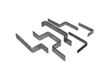 | Sheet Metal Parts Precision Bus Bar Fabrication for Electrical & Industrial Applications Param Controls manufactures and supplies Bus Bar Fabrication using quality... View product → |
Frequently asked questions
How do you determine the required copper bus bar size?
Start with continuous current and the allowable temperature rise in the completed assembly, then adjust the copper section for ambient heat, grouping, enclosure ventilation, and installation conditions.
What installation conditions affect bus bar current capacity?
Ambient temperature, enclosure size, ventilation, nearby heat sources, phase grouping, spacing, orientation, and the number of conductors carrying current all affect temperature rise.
What copper bus bar specifications must be defined for production?
Define copper grade, cross-section, length, hole pattern, bend dimensions, edge condition, plating, joint details, insulation, tolerances, and the required inspection documents.
Why do fault forces affect bus bar design?
Short-circuit current creates electromagnetic forces between conductors. Bus bars need suitable supports, spacing, clearances, and joints to withstand those forces without excessive movement or damage.