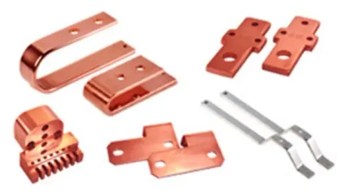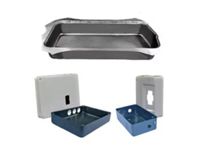
A complex deep-drawn part begins with more than an outside diameter and a material grade: the manufacturer must translate loads, interfaces, tolerances, finish, and production volume into a forming sequence that will not wrinkle, tear, distort, or fail inspection. By the end, you will know what to submit, how drawability is assessed, which tooling and secondary operations may be required, and how to compare prototype, low-volume, and repeat-production proposals.
Key takeaways
- Define function, geometry, material, tolerances, and quantity before requesting a quote.
- Test drawability before cutting production tooling.
- Use staged forming when one draw cannot produce the geometry safely.
- Compare tooling, inspection, finishing, and production costs together.
How a manufacturer turns your component requirement into a production definition
A manufacturer cannot judge whether deep drawn sheet metal parts are feasible from an outline alone. The production definition must state the part’s function, geometry, material behaviour, critical tolerances, and the quantity required.
- Provide the finished dimensions: overall height, diameter or width, flange size, bottom radius, internal corner or punch radius, drawing depth, and any taper.
- Name the material grade, temper, sheet thickness, grain direction requirement, and permitted substitutes. If the wall must remain uniform, specify a minimum finished thickness rather than assuming it will equal the starting sheet thickness.
- Mark every tolerance, datum, hole, slot, bead, embossment, weld point, and joining feature. Identify holes near a drawn radius because they may need piercing after forming.
- State the required surface finish, coating or plating, visible-face limits, electrical bonding points, operating temperature, pressure, vibration, and application loads.
- Give the annual quantity, batch size, prototype deadline, and expected service life so the process can include blanking, drawing, redrawing, ironing, trimming, piercing, forming, joining, or machining.
The manufacturer then checks the depth-to-diameter relationship, blank-holder needs, corner radii, and likely material flow. A first-draw limiting draw ratio around 1.6–2.2 is only a screening figure; grade, lubrication, tooling, thickness, and grain direction can shift it. Sharp radii raise tearing risk, while excessive flange material encourages wrinkles.
A production definition records these risks before tooling begins.
How drawability, material, and process choice are assessed before tooling
Deep drawing is suitable only after comparing geometry, material behaviour, and the required production route—not by depth alone. The manufacturer checks the depth-to-diameter ratio, wall thickness, bottom geometry, flange size, tolerances, surface finish, production quantity, and application loads before designing a die.
1. Calculate the blank diameter divided by the punch diameter. A first-draw limiting draw ratio of about 1.6–2.2 is a screening range, not a pass/fail rule. Grade, temper, thickness, grain direction, lubrication, tooling radii, and blank-holder force can move the limit substantially.
2. Match the material to the strain and service conditions. Deep-drawing grades with higher ductility suit severe shapes; higher-strength grades can reduce thickness or improve load capacity but raise tearing risk. Confirm that the selected sheet thickness supports the load, corrosion requirement, welding method, and minimum finished-wall thickness.
3. Set the forming approach around material flow. Insufficient blank-holder force allows flange wrinkling; excessive force restricts flow and causes tears. Controlled force, draw beads, and variable pressure provide better control than relying on a fixed die gap.
Corner radii are checked against the material and draw severity. A sharp internal corner concentrates strain and can tear; increasing the punch or die radius may allow one draw, while a small packaging radius may require redrawing, ironing, or sizing.
The final decision may be a process chain rather than one stroke: blanking, drawing, redrawing, ironing, trimming, and later piercing or forming. Holes near a drawn radius are usually pierced after forming because pre-pierced features can shift or distort.
How tooling and multi-stage forming handle difficult geometry
A hole or slot near a drawn radius can shift or distort if pierced in the flat blank. Complex components therefore use a process chain: form the shell first, then add features that depend on its final geometry.
Deep drawing tooling begins with blank diameter, punch and die design, corner radii, clearance, and blank-holder control. A blank diameter that is too large increases flange wrinkling; too small leaves insufficient material for the wall and flange.
1. Blank the sheet and make the first draw. Controlled blank-holder force and draw beads regulate material flow: too little restraint causes wrinkles, while too much causes tearing.
2. Redraw the part through dies with progressively smaller diameters when the required depth exceeds one draw. Each stage uses a smaller reduction, often about 15–25%, to limit wall fracture, wrinkling, and loss of concentricity. Add intermediate annealing when work hardening reduces formability.
3. Iron the walls or perform a sizing operation when uniform thickness, tight diameter, or a precise internal fit matters. Ironing improves dimensional consistency but increases forming load and can expose thinning near the punch radius.
4. Trim the flange after forming, then pierce holes, slots, beads, and embossments in dedicated stations or a transfer tool. Finish with welding, machining, tapping, or other joining operations only after forming has stabilised the part; otherwise later deformation can misalign the assembly.
Inspect minimum wall thickness and critical features after each operation, not only at final inspection.
How first-run parts are inspected, finished, and approved
A first-article inspection proves that the formed part meets the drawing in its final three-dimensional state, not merely as a laser-cut blank. The manufacturer establishes the drawing datums, then uses CMM inspection or a height gauge to verify overall dimensions, flange location, hole position, and profile.
Go/no-go gauges confirm repeatable mating features, while wall-thickness measurement checks thinning near punch radii and thickening or wrinkling in the flange.
The inspection record should show four separate proofs:
- Dimensional: Record critical measurements against the drawing, including datum relationships, hole diameters, and formed-wall locations. A flat-sheet laser report cannot prove the final shape.
- Electrical: Check ground continuity or bonding resistance across studs, doors, panels, and joined parts. Mask bonding surfaces before powder coating, or remove coating locally and use specified bonding hardware or jumpers.
- Surface: Inspect burrs, dents, scratches, edge coverage, powder-coat thickness, cure, threaded-hole masking, and coating buildup. A clean-looking finish can still prevent a gasket from seating or a fastener from reaching its torque.
- Assembly: Fit the part with mating components, checking holes, hinges, flanges, gaskets, clearances, and fastener engagement rather than relying on nominal dimensions alone.
The manufacturer closes the first-article inspection with a deviation record for every failed characteristic. Tool compensation, the flat pattern, or a sizing operation is changed when springback or tool wear affects fit, then critical checks are repeated.
Production approval follows only after the signed inspection results, material evidence, coating records, and assembly sample meet the agreed acceptance criteria.
How to compare suppliers, production volumes, and total project cost
The lowest unit price is not necessarily the lowest project cost. Compare each supplier’s quotation against the same drawing, production volume, material grade, tolerance plan, and process chain, including blanking, drawing, redrawing, trimming, piercing, joining, inspection, and packaging.
| Option | Tooling and setup | Unit-cost pattern | Best fit |
|---|---|---|---|
| Prototype production | Soft or modified tooling; confirm whether custom tooling cost is refundable or transferable | Highest unit price, but limits early investment | Design validation and fit checks |
| Low volume | Dedicated tooling may be avoidable; setup and minimum-order charges matter | Tooling amortisation can outweigh the part price | Limited releases or uncertain demand |
| Repeat production | Hardened production dies, defined maintenance, and spare inserts | Lowest stable unit cost after tooling recovery | Forecastable orders and long service life |
Ask for a costed quotation that separates dies, presses, secondary operations, material scrap, setup, first-article inspection, maintenance, freight, and engineering changes. A quote that hides piercing or sizing inside “processing” gives you no basis for comparing suppliers.
Check how the supplier will handle a failed first article. The agreement should identify functional datums, rework limits, approval ownership, and whether the supplier updates the flat pattern or forming compensation after fit validation.
- Compare press capacity, available draw depth, controlled blank-holder force, and inspection equipment.
- Confirm minimum order quantity, lead time for replacement tooling, material-certification format, and traceability documentation.
- Price three scenarios: prototype, planned annual quantity, and a demand increase.
Param Controls should be compared on this same evidence, not on a headline price; a slightly higher quote can be cheaper when it prevents distorted holes, repeated setup, or undocumented material changes.
Related products
 | Sheet Metal Parts Precision Deep Drawing Solutions for Industrial Applications Param Controls manufactures and supplies Deep Drawn Sheet Metal Parts designed for a... View product → |
 | Single Phase Deep Drawn Metal Meter Box Durable & Precisely Manufactured Meter Boxes for Single-Phase Applications Param Controls manufactures and supplies Single Phase Deep Drawn Metal... View product → |
Frequently asked questions
What information does a manufacturer need to define a deep drawn part?
Provide the part’s function, complete geometry, material grade and thickness, critical tolerances, surface requirements, and expected quantity.
How is deep drawability assessed before tooling?
The manufacturer reviews the geometry, blank size, draw depth, radii, material behaviour, thickness, and likely forming sequence before selecting tooling.
When does a complex deep drawn component need multiple forming stages?
Use multiple stages when the required depth, shape, wall profile, or material movement exceeds what one draw can form without tearing or excessive thinning.
How are first-run deep drawn parts approved?
Inspect first-run parts against drawing dimensions, material and thickness requirements, surface condition, and functional fit before approving production.
What should you include when comparing deep drawn sheet metal suppliers?
Compare engineering support, tooling design, process capability, inspection records, finishing control, production volume, lead time, and total project cost.